Introduction
This article is part of a series discussing methods for adding sensing capabilities to a DIY telescoping pole project made from EMT conduit. This article presents:
Seven different methods for sensing the extension length of a telescoping pole made from EMT conduit!
An in-depth look at the photoresistor-based technique among that list of methods.
While the extended length of a telescoping pole can be simply measured using a tape measure, a system for continuously taking such measurements is useful for many different telescoping pole applications and projects:
Know if the pole has slipped
Set a repeatable length (e.g. deployable fruit picker)
Flagpole height measurement, at full mast, half mast, or anywhere in-between
Set the height of an archery or hunting target
Use the telescoping pole itself as a measuring stick
And more!
This article will show you how to add extension-sensing to an EMT conduit telescoping pole by utilizing low-cost, off-the-shelf components:
1", 3/4", and 1/2" EMT conduit from your local hardware store
Photoresistor/light dependent resistor (LDR)
An Arduino microcontroller
And some additional electronics!
Disclosure: Some of the links in this article are affiliate links. This means that, at zero cost to you, I will earn an affiliate commission if you click through the link and finalize a purchase.

Telescoping Pole Extension Sensing Methods
There are many methods to add extension sensing capabilities to a telescoping pole. We summarized seven unique sensing methods in our infographic below, comparing the pros and cons between the different methods. More details regarding each method are shared following the infographic. Feel free to save the image as a reference for whenever your next DIY telescoping pole project requires an extension-sensing solution!

Elaborating on the different types telescoping pole extension-sensing methods:

1. Rolling Wheel
This sensing method relies on tracking the number of turns a contacting wheel has undergone against the pole.
Two types of sensors are readily available for purchase, and are compatible with an Arduino microcontroller. The extension distance of the pole is related to the number of turns of the contact wheel, which is tracked by one of the two sensor choices below.
Encoders such as the above output two pulse signals (channel A and B), which are read and processed by the Arduino using a library such as this, to determine the current position of the encoder based on the sum of the detected pulses along with their direction (clockwise or counterclockwise.)
Encoders can rotate continuously, without needing to worry about hitting a hard stop. These sensors measure the change in the position of the wheel, not its absolute position.
The resistance of a potentiometer varies linearly with the number of times the potentiometer has turned.
One drawback of using a potentiometer as a contact wheel sensor is that a hard stop limit may be hit during operation. However, unlike an encoder, the potentiometer measures the absolute rotational position of the wheel, so extension measurements are not dependent on the history of wheel movement.

2. String potentiometer/draw wire sensor
A wire is attached to the tip of the telescoping pole, and a spring element (such as those found inside a badge reel) retracts the cord when the pole is shortened.
As in method #1 above, a rotational sensor such as a rotary encoder or a multi-turn potentiometer, is again used measure the length of the pole.
Off-the-shelf draw wire sensors exist, and they can be expensive, but some offer very large measurement ranges which may be required for your particular project:
Cost-friendlier draw wire sensors require DIY solutions, such as the following shared on YouTube:

3. Non-reflectance light sensing
This sensing method uses a light emitting diode (LED) in the base of the pole, and a light sensor mounted in the tip of the pole, to measure the pole's length.
Two types of low-cost light sensors are:
Photoresistor/light dependent resistor (LDR)
The electrical resistance changes in the presence of light. Therefore, use this sensor in a voltage divider circuit to read it using an Arduino.
Assortment kits such as this provide multiple photoresistors with varying degrees of sensitivity and response time, depending on your specific project's needs.
Photodiode - can be used in one of two modes (more details here). An operational amplifier is required for both modes of operation.
Photovoltaic mode - used for applications where the intensity of the light is very low, i.e. when your LED is dim, or is far away from the photodiode.
Photoconductive mode - used when a faster sensor response is desired.
The LED which shines on the sensor should be chosen to match the most sensitive wavelength of the sensor. For example, if a sensor is most sensitive to a light wavelength of 940nm, then the LED should also output 940nm.
Here is an example assortment of photodiode/LED pairs with matching wavelengths.
Low-cost photoresistors are typically more sensitive to green light than to red or blue light, so a green LED is most suitable for typical photoresistors.
This assorted kit, for example, is rated for a wavelength of 540nm (i.e. green light.)
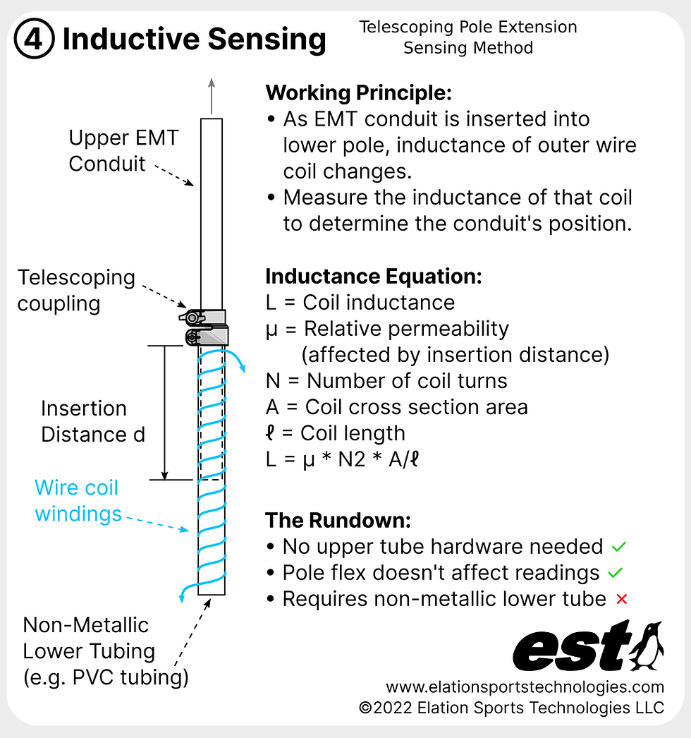
4. Inductive sensing
The total inductance of a wire coil is measured to determine your telescoping pole's extension. The outer tube must be made of a non-metallic material such as plastic, and the inner tube must be made of a metallic material (e.g. EMT conduit.)
As the inner tube moves through the center of the wire coil, its inductance changes. That change in inductance can be measured using a circuit such as the one presented by YouTuber Electronoobs.
In a nutshell, the wire coil is connected in parallel to a capacitor and is powered by the Arduino. When the power from the Arduino is removed, the wire coil and capacitor will oscillate.
An LM339N chip is used to turn those oscillations into on-off (i.e. binary/digital) pulses. A frequency divider chip such as the 74HC04 line is used to decrease the frequency of the pulses so that the Arduino can more easily count them.
The frequency of the pulses counted by the Arduino is related to the position of the inner tube inside the wire coil, and therefore to the pole's extension.
The equation for the inductance of an inductor coil can be found here.
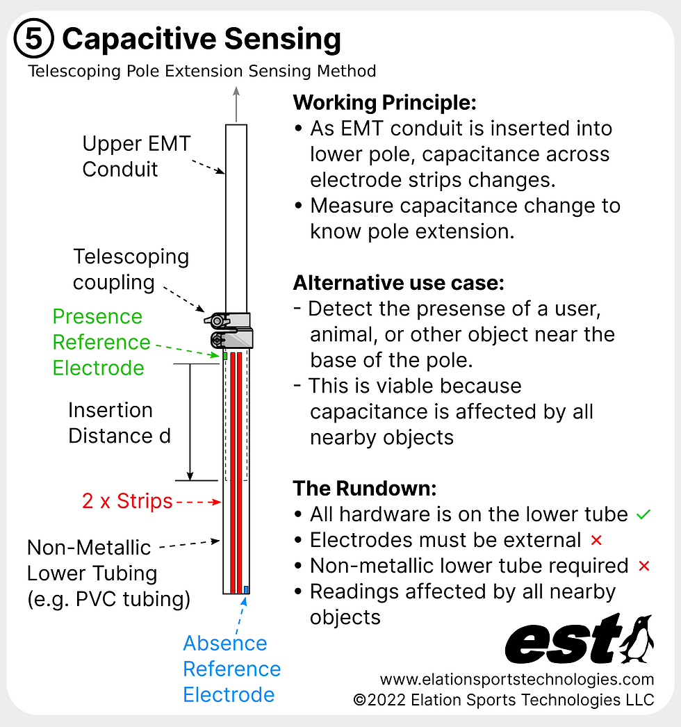
5. Capacitive strip
The capacitance between two long electrode strips is affected by the presence of an inner tube (which can be EMT conduit or another material), again through the surface of an outer, non-metallic tube.
In addition to the long pair of electrodes that runs lengthwise along the outer tube, two additional electrodes are positioned:
Where the inner tube is always present, near the telescoping coupling.
Where the inner tube will never be present, near the base of the outer tube.
The electrodes can be made simply from adhesive-backed copper tape. Wires are soldered directly to the tape and connected to a capacitance-detecting circuit such as the FDC1004.
The electrodes will have a voltage potential across them. Therefore, if a user is expected to handle the pole, or if the pole will be used outdoors, the electrodes should be electrically insulated to prevent shorts.
For safety, only low voltages should be used to power the electrodes!
If only the extension of the pole is to be measured, other objects must be kept away from the electrodes, because they are affected by the presence of all nearby objects, not just the inner tube.
Alternatively, this property can be taken advantage of - for a pole of unchanging length, the presence of a user, animal or other object near the base of the pole can be detected.

6. Conductive elastic cord
A stretchable conductive cord is anchored to the base and the tip of the pole.
As the conductive cord stretches, its resistance changes. The cord, acting as a resistor, is measured with a simple voltage divider circuit. A given resistance value corresponds to a given pole length.
The concept is straightforward, and it can be hidden inside the telescoping pole, but it has its limitations:
The conductive cord must be electrically insulated from the EMT conduit inside which it is housed, or else that contact will affect the cord resistance measurements.
The cord's mechanical properties (e.g. it's ability to spring back quickly) may change over time, making the repeatability of sensor readings questionable.
The length of the cord and the pole must be carefully chosen to function within the bounds of the cord's stretching limit (e.g. up to 200% stretch.)

7. Reflectance sensor
A signal that is emitted from the base of the pole and, reflected off of a panel at the tip of the pole.
Three types of possible reflectance sensors include:
Ultrasonic sound sensor - emits ultrasonic soundwaves. Examples:
Time of Flight (TOF) sensor - measures the time required for an emitted light pulse to bounce off of its target, in order to determine the distance to the target. Examples:
Infrared light reflectance sensor - outputs invisible infrared (IR) light, the intensity of which decreases as the target distance increases. The reflected light is measured using a photodiode. An example IR reflectance sensor:
While these sensors are commonly used in beginner Arduino projects, their wide emitting angle make them a challenge for use with telescoping poles, because the reflecting panel at the pole tip must be large enough to properly reflect back to the sensor and thus be detected.
Photoresistor Circuit
For this article, we explore the non-reflectance light sensing (photoresistor) method for a DIY telescoping pole made from EMT conduit. The general working principle is:
A green LED is installed in the base of the pole.
A pair of photoresistors is installed in a cap at the tip of the pole.
The sensor readings change depending on their distance to the LED - we can therefore use the readings to determine the extension distance of the telescoping pole.
The tip of the EMT conduit telescoping pole can both rotate as well as extend/retract, but we only want to measure the extension, not the rotation angle. In order to decouple the tip extension from its rotation angle, 2 x light-detecting resistors (LDRs/photoresistors) are installed in the tip, 180 degrees out of phase from one another, and the average of the two sensor readings is read by the Arduino microcontroller. The two photoresistors, being diametrically opposed in the tip cap, will theoretically together provide an output that is independent of the tip's rotation angle, removing its effect on the final reading.
The first step in creating this project is to construct the telescoping pole. Creating a telescoping pole from EMT conduit is easy using the Elation Sports Technologies telescoping coupling system. Here's how we did it:
Supplies
1 x Ultra-bright clear green emitting LED from Lighthouse LEDs
1 x Soldering iron
(Optional) 1 x JST-SM connectors assortment
(Optional) 1 x IWISS wire-crimping tool
(Optional) 1 x FDM 3D printer
(Optional) 1 x 1.75mm black PLA filament
Telescoping Pole Setup
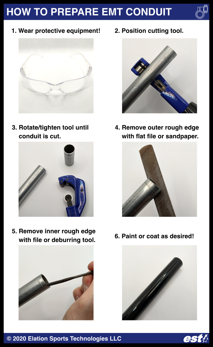
First, prepare the pieces of EMT conduit which will telescope inside of one another:
Wear protective equipment (e.g. safety glasses). Safety first!
Mark the desired cut length for the EMT conduit using a marker. For this article, we used three 5-foot lengths of 1", 3/4", and 1/2" EMT conduit.
Use a rotary cutting tool to cut the conduit to length.
Remove the sharp edge on the cut using a metal wire, or a rotary deburring tool or reamer.
Process the conduit as desired (paint, powder coat, etc.)
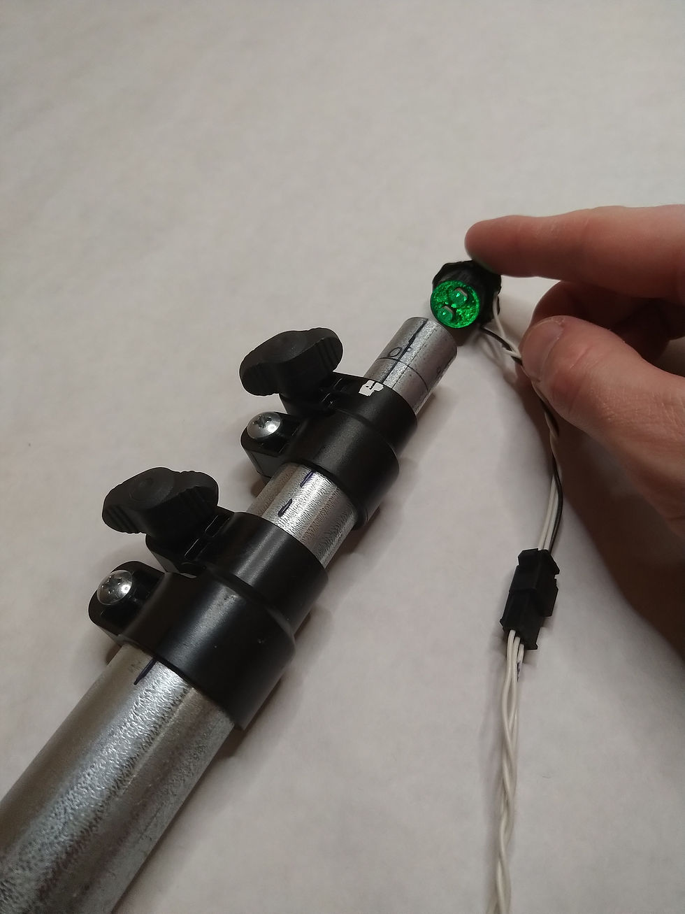
Assemble your telescoping pole - creating a telescoping pole from EMT conduit is easy using the telescoping coupling/clamp system from Elation Sports Technologies:
Press-fit the inner sleeve onto the smaller piece of conduit.
Install the injection-molded coupling/clamp onto the larger piece of conduit using a Phillips head screwdriver.
Extend the pole to the desired length by sliding the smaller piece of conduit, and then tightening the hand knob.

Next, we will prepare the electronics and mount them to the pole.
LED and Photoresistors Installation
To install the LED and LDRs/photoresistors into the telescoping pole, several mounts will need to be 3D-printed. All the models can be downloaded for free from Thingiverse, here. Assembly steps:
3D-print the LED and photoresistor mounts, and the solderless breadboard mount for the Arduino microcontroller.
Install the LED and photoresistors into their mounts and add hot glue to secure them.
Solder wires to the leads on the LED and photoresistors, add heat shrink to insulate the soldered connections, and then crimp JST-SM connectors to those wires so they can be easily connected/disconnected.
Install the LED and photoresistor mounts onto the base and the tip of the telescoping pole, and if needed, secure them with a dab of hot glue or with tape.
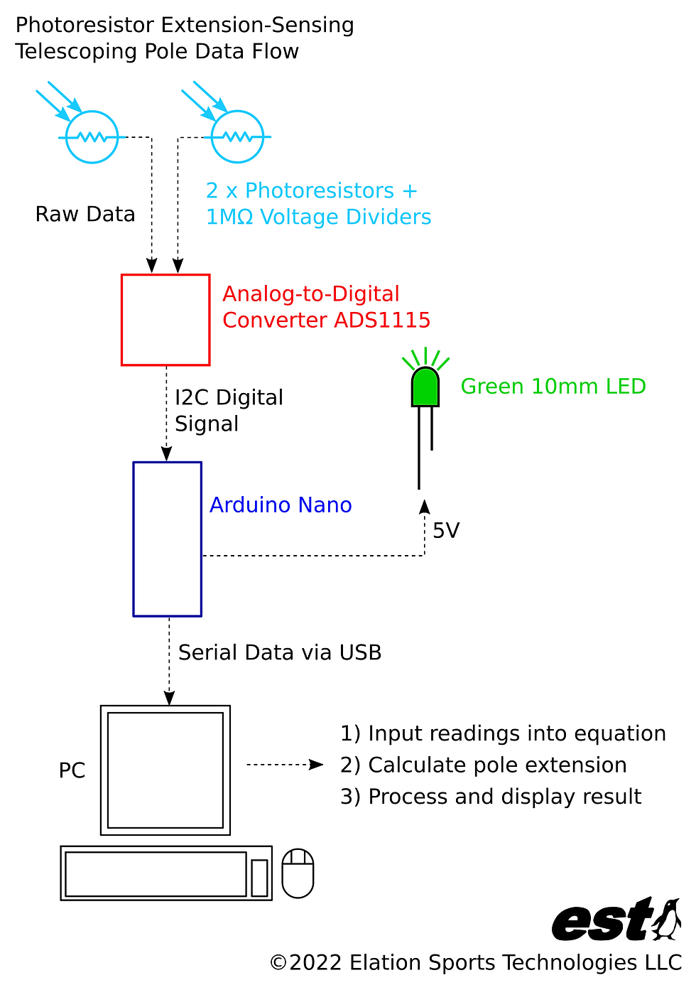
Connect the remainder of the components as indicated in the schematic below.
The purpose of the ADS1115 (analog-to-digital converter/ADC) is to provide higher resolution (16-bit, or 65536 units of resolution) measurements from the photoresistors, as opposed to using the Arduino's on-board ADC can provide (10-bit, or 1024 units of resolution.)


Code
The Arduino Nano runs a code that continuously takes measurements from the 2 x photoresistors, and outputs that data to a PC over Serial protocol via a USB-mini cable. The PC runs a Python script that records the Arduino's output data. Alternatively, the Arduino software's Serial Monitor can be used to see that output data.
The scripts and example data are available on GitHub:
Sensing_Pole_Extension_Photoresistor_Clean.ino
The code running on the Arduino Nano, which reads the data from the ADS1115 (analog-to-digital converter) leading from the 2 x photoresistors.
The Arduino is connected to your PC via a USB-mini cable.
Serial_Logger_Clean.py
Python script running on PC, which logs all the data being output by the Arduino over Serial communication
Photoresistor Calibration Data.csv
A table (.csv file) of data, assembled by the user and listing the 2 x photoresistor readings for different pole extension lengths.
This file is an example of how the data should be formatted to be read by the next Python script in this list.
Sensing Telescoping Pole Extension Photoresistor Calibration - Clean.py
Python script that reads in the calibration data and determines the linear fit coefficients (i.e. the calibration coefficients.) Those coefficient values are output to the next item in this list, a short .csv file.
Calibration Fit Parameters.csv
Calibration linear fit coefficients.
Log_19Dec2021_1444PM.csv
The photoresistor data collected from the Arduino during operation of the telescoping pole following the calibration step. If the pole was calibrated correctly, then this new photoresistor data can be processed to determine the pole's extension over time.
Photoresistor Extension Sensing Pole Demonstration - Clean.py
Processes the above photoresistor usage data, and generates a plot of the pole extension over time.
Also creates an animated bar chart of the data (as seen in the video linked in this article.) Requires that the video processing tool FFMPEG be downloaded - it can be found via a quick Google search, or directly downloaded from their original website: www.ffmpeg.org
Calibration
Here are the calibration steps, which are used to relate the photoresistor readings to the extension length of the telescoping pole:
Mark extension positions along the tip of the telescoping pole, for example at 5, 10, 15, 20, and 25 inches of extension.
Plug the Arduino into the PC, and verify that data is being received by the PC.
For each extension length, record the readings from the two photoresistors.
Take the average of the photoresistor measurement values, and plot them against the extension length - that plot should appear linear (i.e. look like a straight line.)
Take a linear fit of that data - the Python code (item #4 above) posted in the Github link can perform the linear fit. The coefficients that define this linear fit are all that are required to the photoresistor readings to the pole's extension.
The linear equation relating the pole extension (E) to the average photoresistor reading (R) is defined as follows:
E = m*R + b
where:
m = the first linear fit coefficient, representing the slope of the line
b = the second linear fit coefficient, representing the value where the line crosses the zero-reading axis.
Example calibration data and the associated plot are shown below. Note that the average of photoresistor #1 (blue) and photoresistor #2 (orange), form a near-perfect averaged line (green.)
Example calibration data for the photoresistors (LDRs):

Linear fit coefficients:
m = 0.010678
b = -24.98
With the calibration function and its coefficients defined, we can determine the telescoping pole length from the photoresistor readings!
Demonstration
To demonstrate that the calibration was successful, we recorded a video and collected photoresistor readings while arbitrarily extending, retracting, and twisting the telescoping pole. The plot shares the output from the two photoresistors over time. The demo video below can be found on the official Elation Sports Technologies YouTube channel!

The telescoping couplings used to create this project are available for purchase now from Elation Sports Technologies!
Check out our other blog posts for more inspiration for your next EMT conduit project!
Austin Allen
Founder and Owner
Elation Sports Technologies LLC

Comments